Aphex 320D Compellor

What is a Compellor? In short it is a Compressor-Leveler-Limiter. The device is specifically designed for the transparent control of audio levels.

It operates as a stereo processor or as a two-channel (mono) processor supporting independent channel control.

The device includes 3 interactive gain controllers:

– Frequency Discriminate Leveler
– Compressor
– Limiter

Additional features include a Dynamic Release Computer (DRC), Dynamic Verification Gate (DVG), and a Silence Gate.

The original device (model 300 Stereo Compellor) was released in 1984. The product line evolved and culminated in 2003 with the release of the 320D. Through the years the Compellor has been widely used in professional broadcast, post houses, recording studios, and live venues.

In 2004 I purchased a used model 320A from a radio station. The “A” reference indicates it’s analog circuitry. I’ve used the 320A for countless audio file and tape transfers, post production processing, Telephone/Skype recording sessions, and monitoring. The device provides three selectable Operating Levels … +8dBu, +4dBu, and -10dBV.

Recently the complex level and gain reduction metering for the right channel failed. I replaced the faulty 320A with a 320D. This version features digital and analog I/O with common selectable (analog) Operating Levels (+4dBu, and -10dBV).

At some point my faulty 320A will be shipped out to Burbank California for authorized service.

320D – Automatic Processing and Detection

As noted Aphex classifies the Compellor as a Frequency Discriminant Leveler. It responds slower and less aggressively to low frequencies. In essence low frequency energy will not initiate gain reduction.

A Dynamic Release Computer (DRC) instantiates program dependent compression release times.

The Dynamic Verification Gate (DVG) computes the historical average of peak values and verifies whether measured values exceed or are equal to the historical value. When the signal level is below the average, leveling and compression gain reduction is frozen.

Controls

The device Drive control sets the preprocessed VCA gain. Higher settings yield a higher level of gain reduction (VCA refers to Voltage Controlled Amplifier).

The Process Balance control allows the operator to fine tune the Leveling and/or Compression balance and weighting. Leveling is a slow method of gain reduction. It maintains transient retention and wider dynamics. The Compression stage works faster and acts more aggressively on inherent dynamics. The key is by combining both modes, the processed output will be very consistent

A Rate (speed) toggle option is provided: Fast, suitable for speech/voice, or Slow, suitable for program material such as produced TV and/or Radio programs.

The device Output control normalizes the processed audio to 0VU.

Silence Gate: Aphex stresses – this is not an audio gate! It is a user defined threshold parameter. When the signal drops below the threshold for 1 sec. or longer, the Silence Gate freezes the VCA gain. This prevents the buildup of noise during pauses and/or extended passages of silence.

The device Limiter features a very fast attack and high threshold. It is designed to prevent occasional high transient activity and overshoots.

A Stereo Enhance mode is available on the 320A and 320D models. When activated it widens the stereo image. It’s effect is dependent upon the amount of applied compression.

Metering

The 320D Compellor features three, bi-color (red, green) LED metering modes: Input, Output, and Gain Reduction. For Input/Output metering – the red LED’s indicate VU/average. Green LED’s indicate peak level.

When the meter is set to display gain reduction (“GR”), the green LED’s indicate total gain reduction. Depending on the Process Balance control weighting – a floating red LED may appear within green LED instances. The floating red LED indicates Leveling gain reduction. If Leveling gain reduction is in fact occurring, the total gain reduction will be indicated by the subsequent green LED(s).

Below are 4 examples:

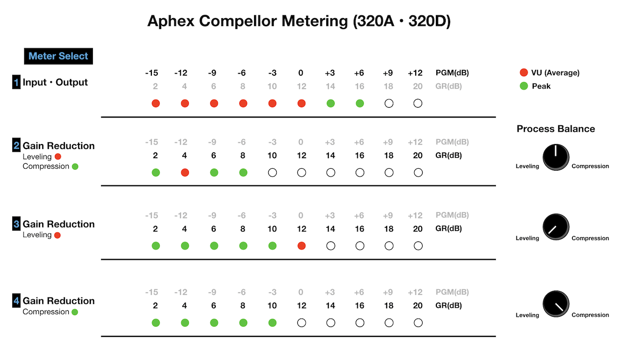
Example 1 displays Input or Output metering with an average (red) level of 0VU and a peak (green) level of +6dB. This translates to a +4dBu average level and a +10dB peak level (analog OL set to +4dBu).

Example 2 displays 4dB of Leveling Gain Reduction and 8dB of Total Gain Reduction.

Example 3 displays 12dB of Leveling Gain Reduction.

Example 4 displays 10dB of Compression Gain Reduction.

**Notice the position of the Process Balance control for examples 2, 3, and 4.
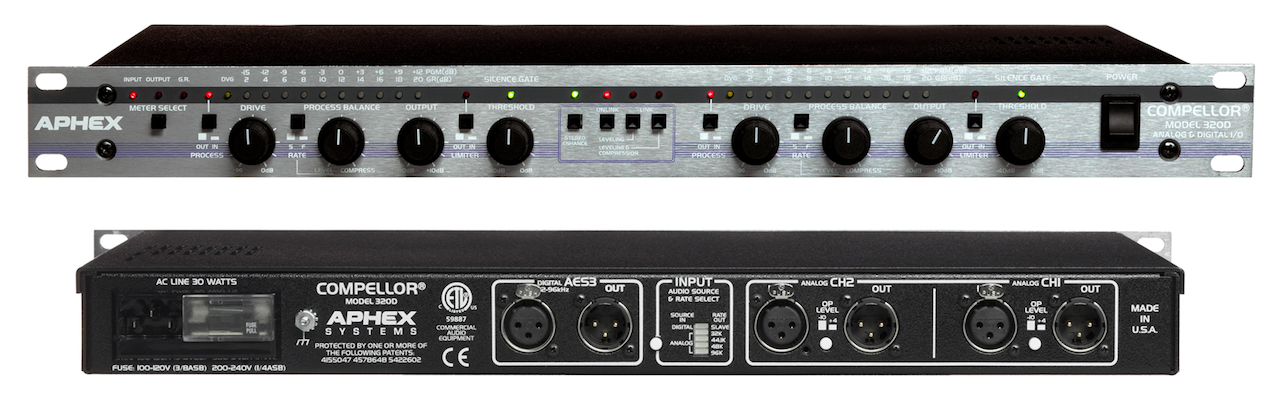
320D I/O

The 320D is essentially an analog processor utilizing standard XLR I/O jacks. The device also includes AES/EBU XLR jacks along with an internal DAC for digital I/O. The Input mode and/or Sample Rate is user selectable.

When implementing digital I/O – the Incoming audio is converted to analog as it passes through the device. The audio is then converted back to digital and output accordingly.

The digital input is calibrated internally and matches -20dBFS to 0VU on the Compellor’s meter. The +4dBu/-10dBV Operating Level options only affect the analog I/O.

Notes:

The Aphex Compellor is a long standing, highly regarded, and ubiquitous audio processor. It has been an integral multipurpose tool for me for 12+ years. My newly purchased (used) 320D is in near mint condition. In fact it looks and feels as if it was hardly used by the previous owner.

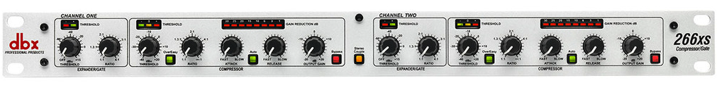
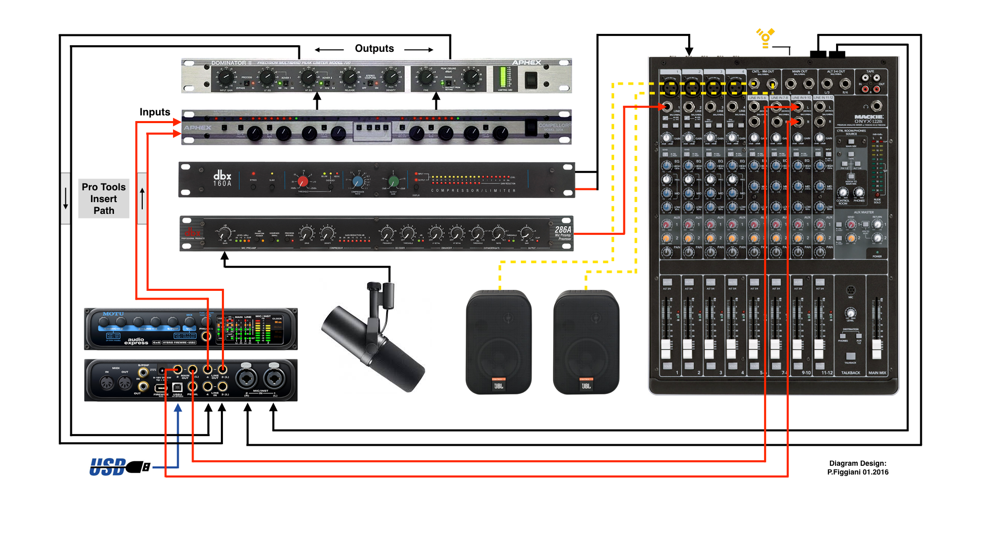
My system includes additional Aphex audio processors (651 Compressor, 109 EQ, 622 Expander/Gate, and a 720 Dominator II Multiband Peak Limiter). As well, a Mackie Onyx 1220i Mixer, Motu I/O, dbx 160A Compressor, dbx 286A Mic Processor, Marantz CF Recorder, and a Telos One Digital Hybrid. All components, with the exception of the 286A – are interfaced through a balanced Patchbay.

A typical processing/monitoring chain will pass system audio through the Compellor, followed by the 720 Peak Limiter. The processed audio is ultimately routed to the system’s Main Output(s). This chain optimizes playback of poorly produced Podcasts, VO’s, live streams, or videos. The routing is implemented via Patchbay.

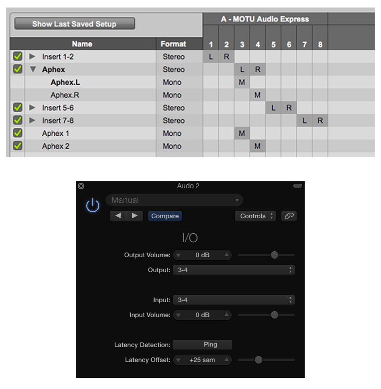
A typical audio processing chain will route Pro Tools audio out via hardware insert (or bus, alternative output, etc.) through the Compellor (or a more complex chain) and returned in Pro Tools. In this scenario I use a set of assignable interface line inputs/outputs. The routing is implemented via Patchbay. I document the setup and use of hardware inserts here.

-paul.

Loudness Measurement and Silence

Consider this: Two extended segments of audio, Loudness Normalized (or mixed in real time) to the same Integrated Loudness Target.

Segment (A) is fairly consistent, with a very limited amount of intermittent silence gaps.

Segment (B) is far less consistent, due to a multitude of intermittent silence gaps.

When passing both segments through a Loudness Meter (or measuring the segments offline), and recognizing Integrated Loudness is a reflection of the average perceptual Loudness of an entire segment – how will inherent silence affect the accuracy of the cumulative measurements?

In theory the silence gaps in Segment (B) should affect the overall measurement by returning a lower representation of average Integrated Loudness. If additional gain is added to compensate, Segment (B) would be perceptually louder than Segment (A).

Basically without some sort of active measurement threshold, the algorithms would factor in silence gaps and return an inaccurate representation of Integrated Loudness.

The Fix

In order to establish perceptual accuracy, silence gaps must be removed from active measurements. Loudness Meters and their algorithms are designed to ignore silence gaps. The omission of silence is based on the relationship between the average signal level and a predefined threshold.

Loudness Meter (G10) Gate

The specification Gate (G10) is an aspect of the ITU Loudness Measurement algorithms included in compliant Loudness Meters. It’s function is to temporarily pause Loudness measurements when the signal drops below a relative threshold, thus allowing only prominent foreground sound to be measured.

The relative threshold is -10 LU below ungated LUFS. Momentary and Short Term measurements are not gated. There is also a -70 LUFS Absolute Gate that will force metering to ignore extreme low level noise.

Most Loudness Meters reveal a visual indication of active gating (see attached image) and confirm the accuracy of displayed measurements.

Gate-(480)

Additional “Gate” Generalizations and Nomenclature

A Downward Expander and it’s applied attenuation is dependent on signal level when the signal drops below a user defined threshold. The Ratio dictates the amount of attenuation. Alternatively a Noise Gate functions independent of signal level. When the level drops below the defined threshold, hard muting is applied.

Silence Gate

This is a somewhat proprietary term. It is a parameter setting available on the Aphex 320A and 320D Compellor hardware Leveler/Compressor.

Compellor

When a passing signal level drops below the user defined Silence Gate threshold for 1 second or longer, the device’s VCA (Voltage Controlled Amplifier) gain is frozen. The Silence Gate will prevent the Leveling and Compression processing from releasing and inadvertently increasing the audibility of background noise.

-paul.

Hardware Inserts In Your DAW

It is possible to implement support for use of external hardware processing components within your software DAW. This support is common in music recording and audio post production environments.

When properly implemented, operators have the capability to insert an instance of an external component (or chain) on a DAW audio track just like any other installed third party software plugin.

Besides potential tonal advantages, routing through a specialized external component can be less taxing on the host system’s resources.

Requirements

1 – Your Interface must have an available output (mono or stereo) for routing audio to an external component. You will also need an available input (again, mono or stereo) to accept the processed audio.

2 – Your DAW must support the routing.

Pro Tools and Logic Pro X

In the Pro Tools I/O settings you must define a set of available (and matching) Interface inputs and outputs for signal routing. In Logic Pro X, there is an I/O routing option plugin included in the Utility plugins group.

Have a look at the routing configuration options for both DAWS:

Inserts_small

The upper image displays a Pro Tools Insert Routing matrix. The default audio interface has a total of 8 inputs and outputs available as discrete I/O mono channels. They can remain as such. Alternatively, they can be paired to create four stereo signal paths.

I’ve defined three instances or parent paths of “Aphex” inserts using interface inputs and outputs 3 + 4. My processing chain supports a stereo signal flow or discrete dual mono.

The first Aphex instance is a stereo insert. Clicking the disclosure triangle reveals two associated mono channels that make up the stereo pair. This configuration translates in Pro Tools as a stereo hardware insert or as two discrete mono inserts.

At the bottom of the list I’ve also created two custom mono paths the will pass audio to discrete mono component channels. This alternative solution is unnecessary in this particular configuration. The stereo instance above provides the same level of flexibility with support for mono accessibility. Just be aware of the configuration flexibility.

The lower image displays a Logic Pro X stereo I/O instance as it would appear when inserted on any track. Notice how I am using the same combination of interface channels (3 + 4) to output the signal to external components, and to route the processed audio back into the DAW.

Use Case

Let’s say you are the proud owner of the very affordable and recommended dbx 266xs Dynamics Processor. You would like to use it to pre-process a discrete channel Skype session in realtime. This dbx Compressor, Limiter, and Gate can function as a dual mono processor. With routing properly configured, you can insert mono instances of the hardware processor on discrete tracks in your DAW session. Simply customize settings for each dbx channel and fire away.

266xs_small

My Chain

Over the years I’ve accumulated various analog audio processors by Telos, dbx, and Aphex. In the displayed diagram I disclose part of my current configuration with a few active components.

hardware_inserts-small

Before I get into the Pro Tools insert path configuration, let me explain the basic signal routing:

• I use a Mackie Onyx 1220i FW Mixer in combination with a Motu Audio Express USB/FW Interface. The Mackie controls a POTS line mix-minus using a Telos Digital Hybrid. The mixer also controls signal routing scenarios and recording on a Marantz CF Recorder. I use the mixer’s Control Room outputs to feed the inputs of a power amplifier to drive my JBL near-field monitors.

• The Motu’s Main Outputs are patched to the mixer. This audio is available on the Control Room outputs. I can easily switch back and forth between the mixer and the interface, designating one or the other as the default I/O.

• The mixer also functions as a secondary gain stage for the mic signal path. Notice how the mic is directly connected to the dbx 286A Voice Processor. It’s balanced line output feeds the channel 1 line input on the Mackie. The balanced Mackie Main Outputs are set to deliver a Mic Level signal. They feed the Mic Level inputs on the Motu interface. These inputs can be linked and routed to a single stereo DAW track. Alternatively I can designate the inputs to deliver discrete mono. This is handy when a second mic is integrated

• The dbx160a is a single channel (mono) compressor. It is connected to the Mackie’s channel 2 insert. I can use this device as a serial processor on mixer channel 2. I can also insert it on the channel that returns a telco caller’s POTS audio back to the mixer. In this scenario I can easily bypass it’s use on an insert and instead connect it in-line.

• All system connections are made with balanced XLR and TRS cables.

Not pictured: Aphex Expressor (mono) Compressor, Aphex 622 Expander/Gate, and Aphex two channel Parametric EQ.

Hardware Chain Insert

Let’s focus on the Pro Tools Insert path, instantiated on a stereo audio track:

The two (pictured) devices that I am currently using for external audio processing are by Aphex: 320a Compellor, and the 720 Dominator II. The 320a Compellor is widely used in radio broadcast facilities. This device can be configured to function as a Leveler, Compressor, or a mixture of both. A Process Balance setting controls the Leveling and Compression weighting. It supports stereo and dual mono processing. The current “D” version supports AES/EBU Digital I/O.

The Dominator II is a 3-band Peak Limiter with adjustable crossovers and zero overshoot. This device is also widely used in broadcast facilities and for live performances. The current 722 version features enhanced broadcast processing support, including Pre-Emphasis and De-Emphasis options.

With the Motu interface designated as the default I/0, it’s 3+4 Line Outputs route audio via insert from a Pro Tools audio track to the Compellor’s inputs. The Compellor’s outputs feed the Dominator II’s inputs. It’s outputs feed the Motu’s Line Inputs, routing the processed audio back to the DAW track where the hardware insert was originally instantiated.

A Skype session would be an obvious use option. In this case I would implement discrete mono hardware processing using two separate insert instances. In fact I can use this configuration when recording any audio source, or as a realtime processing option for output, playback, and streaming.

As far as playback, the Motu interface supports a Mix 1 Return option. In essence I can assign my system’s output into Pro Tools. With Input Monitoring activated, I can route the signal through the external processors and monitor the wet audio. This is a handy feature during playback of poorly produced programs.

Audition

Unfortunately Adobe Audition does not support hardware inserts. However there are various ways to integrate your external components in a multitrack session. For example you can assign a track’s output (or outputs) to an available interface output that feeds an external component’s input (or inputs). The processed audio is then routed to available interface inputs. By defining this active interface input as a track input, you essentially route processed audio back into the session.

This signal routing option will work in any DAW. Be aware you run the risk of initiating feedback loops!. To avoid this please make sure the software routing utility for the particular interface is properly configured.

In Conclusion

It is easy to integrate your analog gear in your software DAW. Use case scenarios are endless. Of course support and effectiveness will vary across all components and applications. I will say it’s a pretty cool feature, especially when software versions of coveted analog devices simply do not exist.

-paul.