Real Time Print To Track

Logic and Audition users will be familiar with the term Bounce to Track. This process allows the user to perform an Off-line Mixdown of a selected group of Session Tracks without physically exporting. In most cases the Mixdown appears on a supplemental target Track.

Bouncing Off-line is a time saver. However it can be precarious. It would be irresponsible to submit a finished piece of audio to a client without 100% conformation the bounced delivery file (most likely slated for distribution) is glitch free. In essence it is imperative to throughly check your piece prior to submission.

Off-line Bounce (aka Bounce to Disk) was once notoriously absent from Pro Tools. Avid finally implemented support a few years ago.

In professional Post Production, engineers may perform a real time (On-line) Bounce of a mix Session. The process is commonly referred to as Printing. It requires the operator to sit through the Session in it’s entirety.

Besides glitch detection capabilities, it is possible to edit clips before the playhead reaches their location. As well, you can edit clips and/or sub-segments within a previously completed Print and only re-Print the manipulated segment.

So how is this done? Simple – if the DAW or Interface supports it.

For instance in Pro Tools the user can assign Bus outputs to the input of a standard Audio Track. The key is you can ARM a standard Audio Track to record any signal that is passing through it. This would be the Print Track.

Adobe Audition CC does not support direct Bus Output —>> Audio Track assignments. However, it is still possible to implement a Print workflow (see attached image). You will need a supported Audio Interface with a Mix Return. Simply assign all Session Tracks and Buses to the Main Output. Then add a supplemental Audio Track. Set it’s input to Mix Return. ARM the Track to record and fire away.

-paul.

Adobe Audition Multiband Compressor

I thought I’d clear up a few misconceptions regarding the Multiband Compressor bundled in Adobe Audition. Also, I’d like to discuss the infamous “Broadcast” preset that I feel is being recommended without proper guidance. This is an aggressive preset that applies excessive compression and heavy limiting resulting in processed audio that is often fatiguing to the listener.

audition-multi-480

The Basics

The tool itself is “Powered by iZotope.” They are a well respected audio plugin and application development firm. Personally I think it’s great that Adobe decided to bundle this processor in Audition. However, it is far from a novice targeted tool. In fact it’s pretty robust.

What’s interesting is it’s referred to as a “Multiband Compressor.” This is slightly misleading, considering the processor includes a Peak Limiter stage along with it’s advertised Multiband Compressor. I think Dynamics Processor would be a more suitable name.

Basically the multi-band Compressor includes 3 adjustable crossovers, resulting in 4 independent Frequency Bands. Each Band includes a discrete Compressor with Threshold, Gain Compensation, Ratio, Attack, and Release settings. Bands can be soloed or bypassed.

There is global Peak Limiter module located to the right of the Compressor settings. This module may be activated or bypassed. Without a clear understanding of the supplied settings for the Limiter, you run the risk of generating excessive loudness when processing audio. I’m referring to a substantial increase in perceived loudness.

The Limiter Parameters

The Threshold is the limiting trigger. When the input signal surpasses it, limiting is activated. The Margin is what defines the Peak Ceiling. As you decrease the Threshold, the signal is driven up to and against the Margin resulting in an increase in average loudness. This also results in dynamic range reduction.

Activating the “Brickwall Limiter” feature in the supplemental Options module will ensure accurate Margin compliance. In essence you will be implementing Hard Limiting. Deactivating this option may result in “overs” and/or peaks that exceed the specified Margin.

The bundled Broadcast preset defaults the Limiter Threshold setting to -10.0 dB with a Margin of -0.1 dBFS. Any alternative Threshold settings are of course subjective. I’m suggesting that it may be a good idea to ease up on this default Threshold setting. This will result in less aggressive limiting and a reduction of average levels.

I’m also suggesting that the default Margin setting of -0.1 is not recommended in this context. I would set this to -1.0 dBFS or lower (-1.5 dBFS, or even -2.0 dBFS).

Please note this is not a True Peak Limiter. Your processed lossless audio file has the potential to loose headroom when and if it is converted to a lossy codec such as MP3.

At this point I suggest no changes should be made to the Attack and Release settings.

The Compressors

We cannot discount additional settings included in the Broadcast preset that are contributing to the aggressive processing. If you examine the Ratio settings for each independent compression module, 3:1 is the highest set Ratio. The predefined Ratios are fairly moderate and for starters require no adjustment.

However, notice the Threshold settings for each compression module as well as the Gain Compensation setting in Module (band) 4 (+3 dB).

First, the low Threshold settings result in fairly aggressive compression per band. Also, the band 4 gain compensation is generating a further increase in average level for that particular band.

Again the settings and any potential adjustments are subjective. My recommendation would be to experiment with the Threshold settings. Specifically, cut back by reducing all Thresholds while maintaining their relative relationship. Do this by activating the “Link Band Controls” setting located in the supplemental Limiter Options.

View the red Gain Reduction meters included in each module. Monitor the amount of attenuation that occurs with the default Threshold settings. Compare initial readings with the gain reduction that occurs after you make your adjustments. Your goal is to ease up on the gain reduction. This will result in less aggressive compression. Remember to use your ears!

Output

An area of misinformation for this processor is the purpose of the Output Gain adjustment, located at the far upper right of the interface. Please note this setting does not define the Peak Ceiling! Remember – it is the Margin setting in the Limiter module that defines your Ceiling. The Output Gain simply adds or cuts global output level after compression. Think of if it as Global Gain compensation.

To prove my point, I dug out a short video demo that I created sometime last year for a community member.

With the Broadcast preset selected, and the Output Gain set to -1.5 dBFS – the actual output Peak Amplitude surpasses -1.5 dBFS, even with the Brickwall option turned ON. This reading is displayed numerically above the Output Gain meter(s) in real time.

In the second pass of the test I set the Output Gain to 0 dBFS. I then set the Limiter Margin to -1.5 dBFS. As the audio plays through you will notice the output is limited to and never surpasses -1.5 dBTP. Just keep your eye on the numerical, realtime display.

Video Demo Link

I purposely omitted any specific references to Attack and Release settings. They are the source for a future discussion.

DeEsser?

Here’s an alternative use recommendation for this Adobe Multiband Compressor: DeEssing.

Use the Spectrum Analyzer to determine the frequency range where excessive sibilant energy occurs. Set two crossovers to encapsulate this range. Bypass the remaining associated compression modules. Tweak the remaining active band compression settings thus allowing the compressor to attenuate the problematic sibilant energy.

If you find the supplied Spectrum Analyzer difficult to read, consider using a third party option with higher resolution to perform your analysis.

Conclusion

Please note – in order to get the most out of this tool, you really need to learn and understand the basics of dynamics compression and how each setting will affect the source audio. More importantly, when someone simply suggests the use of a preset, take it with a grain of salt. More than likely this person lacks a full understanding of the tool, and may not be capable of providing clear instructional guidance for all functions. It’s a bad mix – especially when charging novices big bucks for training.

By the way, nothing wrong with being a novice. The point is paid consultants have an obligation to provide expert assistance. Boiler plate suggestions serve no purpose.

-paul.

Audition CC: Loudness Normalization Pt.2 …

In my previous article I discussed various aspects of the Match Volume Processor in Adobe Audition CC. I mentioned that the ITU Loudness processing option must be used with care due to the lack of support for a user defined True Peak Ceiling.

I also pointed to a video tutorial that I produced demonstrating a Loudness Normalization Processing Workflow recommended by Thomas Lund. It is the off-line variation of what I documented in this article.

Here’s how to implement the off-line processing version in Audition CC …

This is a snapshot of a stereo version of what may very well be the second most popular podcast in existence:

Amplitude Statistics in Audition:

Peak Amplitude:0dB
True Peak Amplitude:0.18dBTP
ITU Loudness:-15.04 LUFS

source-(480)

It appears the producer is Peak Normalizing to 0dBFS. In my opinion this is unacceptable. If I was handling post production for this program I would be much more comfortable with something like this at the source:

Amplitude Statistics in Audition:

Peak Amplitude:-0.81dB
True Peak Amplitude:-0.81dBTP
ITU Loudness:-15.88 LUFS

intermediate-(480)

We will be shooting for the Internet/Mobile/Podcast target of -16.0 LUFS Program Loudness with a suitable True Peak Ceiling.

The first step is to run Amplitude Statistics and determine the existing Program Loudness. In this case it’s -15.88 LUFS. Next we need to Loudness Normalize to -24.0 LUFS. We do this by simply calculating the difference (-8.1) and applying it as a Gain Offset to the source file.

The next step is to implement a static processing chain (True Peak Limiter and secondary Gain Offset) in the Audition Effects Rack. Since these processing instances are static, save the Effects Rack as a Preset for future use.

Set the Limiter’s True Peak Ceiling to -9.5dBTP. Set the secondary Gain Offset to +8dB. Note that the Limiter must be inserted before the secondary Gain Offset.

Process, and you are done.

In this snapshot the upper waveform is the Loudness Normalized source (-24.0 LUFS). The lower waveform in the Preview Editor is the processed audio after it was passed through the Effects Rack chain.

lund-method-(480)

In case you are wondering why the Limiter is before the secondary Gain instance – in a generic sense, if you start with -9.5 and add 8, the result will always be -1.5. This translates into the Limiter doing it’s job and never allowing the True Peaks in the audio to exceed -1.5dBTP. In essence this is the ultimate Ceiling. Of course it may be lower. It all depends on the state of the source file.

This last snapshot displays the processed audio that is fully compliant, followed by it’s Amplitude Statistics:

normalized-(480)

stats-audition

In Summary:

[– Determine Program Loudness of the source (Amplitude Statistics).

[– Loudness Normalize (Gain Offset) to -24.0 LUFS.

[– Run your saved Effects Rack chain that includes a True Peak Limiter (Ceiling set to -9.5dBTP) and a secondary +8dB Gain Offset.

Feel free to ping me with questions.

-paul.

Audition CC: Loudness Normalization …

*** UPDATE: Please note this post was written in 2014. The current version of Adobe Audition CC has been greatly enhanced, specifically in regards to the Match Loudness Module. It is now possible to define a True Peak Maximum, as well as Integrated/Program Loudness targets. It is also possible to customize Loudness Normalization Tolerence.

Adobe Audition CC has a handy Match Volume Processor with various options including Match To/ITU-R BS.1770-2 Loudness. The problem with this option is the Processor will not allow the operator to define a True Peak Ceiling. And so depending on various aspects of the input file, it’s possible the processed audio may not comply due to an unsuitable Peak Ceiling.

For example if you need to target -16.0 LUFS Program Loudness for internet/mobile distribution, the Match Volume Processor may need to increase gain in order to meet this target. Any time a gain increase is applied, you run the risk of pushing the Peak Ceiling to elevated levels.

The ITU Loudness processing option does supply a basic Limiting option. However – it’s sort of predefined. My tests revelaled Peak Ceilings as high as -0.1dBFS. This will result in insufficient headroom for both True Peak compliance and preparation for MP3 encoding.

The Audition Match Volume Processor also features a Match To/True Peak Amplitude option with a user defined True Peak Ceiling (referred to as Peak Volume). This is essentially a True Peak Limiter that is independent of the ITU Loudness Processor. For Program Loudness and True Peak compliance, it may be necessary to run both processing stages sequentially.

processor

There are a few caveats …

[– If the Match Volume Processor (Match To/ITU-R BS.1770-2 Loudness) applies limiting that results in a Peak Ceiling close to full scale, any subsequent limiting (Match To/True Peak Amplitude) has the potential to reduce the existing Program Loudness.

[– If a Match Volume process (Match To/ITU-R BS.1770-2 Loudness) yields a compliant True Peak Ceiling right out of the box, there is no need to run any subsequent processing.

Conclusion

If you are going to use these processing options, my suggestion would be to make sure the measured Program Loudness of your input file is reasonably close to the Program Loudness that you are targeting. Also, make sure the input file has sufficient headroom, with existing True Peaks well below 0dBFS.

If you are finding it difficult to achieve acceptable results, I suggest you apply the concepts described in this video tutorial that I produced. I demonstrate a sort of manual “off-line” Loudness Normalization process. If you prefer to handle this in real time (on-line), refer to my article “Podcast Loudness Processing Workflow.”

-paul.

Adobe Loudness Radar Up and Running …

With the release of the Adobe “CC” versions of Audition and Premiere Pro, users now have access to a customized version of the tc electronic Loudness Radar Meter.

LR-Banner

In this video from NAB 2013, an attendee asks an Adobe Rep: “So I’ve heard about Loudness Radar … but I don’t really understand how it works.”

I thought it would be a good idea to discuss the basics of Loudness Radar, targeting those who may not be too familiar with it’s design and function. Before doing so, there are a few key elements of loudness meters and measurement that must be understood before using Loudness Radar proficiently.

Loudness Measurement Specifications:

Program “Integrated” Loudness (I): The measured average loudness of an entire segment of audio.

Loudness Range (LRA): The difference between average soft and average loud parts of a segment.

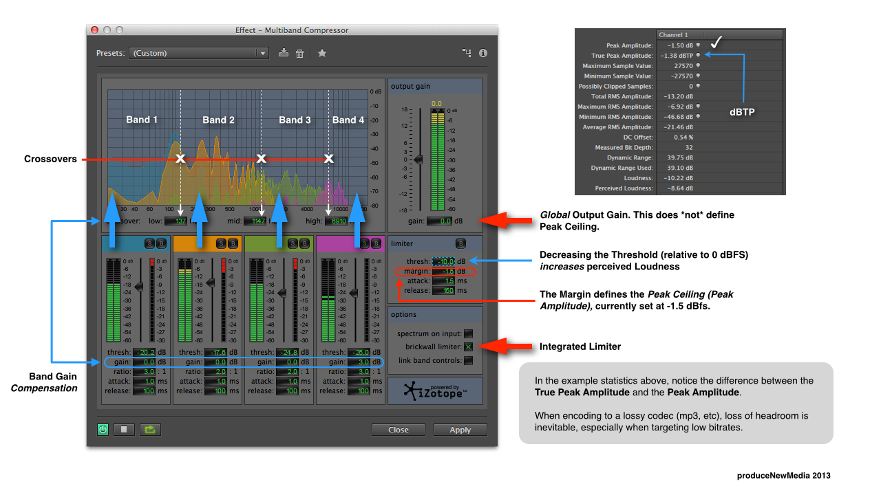
True Peak (dBTP): The maximum electrical amplitude with focus on intersample peaks.

Meter Time Scales:

• Momentary (M) – time window:400ms
• Short Term (S) – time window:3sec.
• Integrated (I) – start to stop

Program Loudness Scales

Program Loudness is displayed in LUFS (Loudness Units Relative to Full Scale), or LKFS (Loudness K-Weighted Relative To Full Scale). Both are exactly the same and reference an Absolute Scale. The corresponding Relative Scale is displayed in LU’s (Loudness Units). 0 LU will equal the LUFS/LKFS Loudness Target. For more information please refer to this post.

LU’s can also be used to describe the difference in Program Loudness between two segments. For example: “My program is +3 LU louder than yours.” Note that 1 LU = 1 dB.

Meter Ranges (Mode/Scale)

Two examples of this would be EBU +9 and EBU +18. They refer to EBU R128 Meter Specifications. The stated number for each scale can be viewed as the amount of displayed loudness units that exceed the meter’s Loudness Target.

From the EBU R128 Doc:

1. (Range) -18.0 LU to +9.0 LU (-41.0 LUFS to -14.0 LUFS), named “EBU +9 scale”

2. (Range) -36.0 LU to +18.0 LU (-59.0 LUFS to -5.0 LUFS), named “EBU +18 scale”

The EBU +9 Range is well suited for broadcast and spoken word. EBU +18 works well for music, film, and cinema.

Loudness Compliance: Standardized vs. Custom

As you probably know two ubiquitous Loudness Compliance Standards are EBU R128 and ATSC A/85. In short, the Target Loudness for R128 is -23.0 LUFS with peaks not exceeding -1.0 dBTP. For ATSC A/85 it’s -24.0 LKFS, -2.0 dBTP. Compliant loudness meters include presets for these standards.

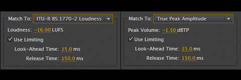
Setting up a loudness meter with a custom Loudness Target and True Peak is often supported. For example I advocate -16.0 LUFS, -1.5 dBTP for audio distributed on the internet. This is +7 or 8 LU hotter than the R128 and/or ATSC A/85 guidelines (refer to this document). Loudness Radar supports full customization options to suit your needs.

Pause/Reset

Loudness meters have “On and Off” switches, as well as a Reset function. For Loudness Radar – the Pause button temporarily halts metering and measurement. Reset clears all measurements and sets the radar needle back to the 12 o’clock position. Adobe Loudness Radar is mapped to the play/pause transport control of the host application.

Gating

The Loudness Standard options available in the Loudness Radar Settings designate Measurement Gating. In general, the Gate pauses the loudness measurement when a signal drops below a predefined threshold, thus allowing only prominent foreground sounds to be measured. This results in an accurate representation of Program Loudness. For EBU R128 the relative threshold is -10 LU below ungated LUFS. Momentary and Short Term measurements are not gated.

• ITU BS.1770-2 (G10) implements a Relative Gate at -10 LU and a low level Gate at -70 LU.

• Leq(K) implements a -70 LU low level Gate to avoid metering bias during 100% silent passages. This setting is part of the ATSC A/85 Specification.

Loudness Radar In Use

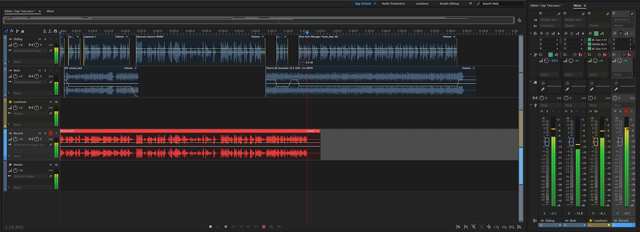
In Audition CC you will find Loudness Radar located in Effects/Special/Loudness Radar Meter. It is also available in the Effects Rack and in the Audio Mixer as an Insert. Likewise it is available in Premiere Pro CC as an Insert in the Audio Track Mixer and in the Audio Effects Panel. In both host applications Loudness Radar can be used to measure individual clips or an entire mix/submix. Please note when measuring an audio mix – Loudness Radar must be placed at the very end of the processing chain. This includes routing your mix to a Bus in a multitrack project.

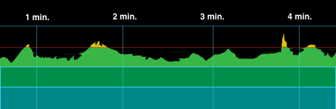
Most loudness meters use a horizontal graph to display Short Term Loudness over time. In the image below we are simulating 4 minutes of audio output. The red horizontal line is the Loudness Target. Since the simulated audio used in this example was not very dynamic, the playback loudness is fairly consistent relative to the Loudness Target. Program Loudness that exceeds the Loudness Target is displayed in yellow. Low level audio is represented in blue.

Each horizontal colored row represents 6 LU of audio output. This is the meter’s resolution.

histrogram

Loudness Radar (click image below for high-res view) uses a circular graphic to display Short Term Loudness. A rotating needle, similar to a playhead tracks the audio output at a user defined speed anywhere from 1 minute to 24 hours for one complete rotation.

LM-480

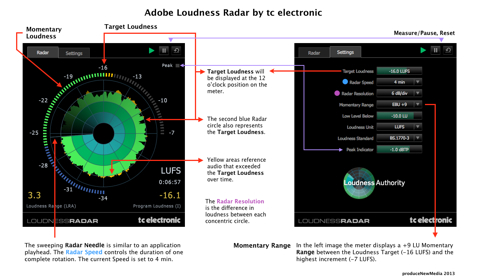
The circular LED meter on the perimeter of the Radar displays Momentary Loudness, with the user defined Loudness Target (or specification target) visible at the 12 o’clock position. The Momentary Range of the LED meter reflects what is selected in the Settings popup. The user can also customize the shift between green and blue colors by adjusting the Low Level Below setting.

The numerical displays for Program Loudness and Loudness Range will update in real time when metering is active. The meter’s Loudness Unit may be displayed as LUFS, LFKS, or LU. The Time display below the Loudness Unit display represents how long the meter is/was performing an active measurement (time since reset). Lastly the Peak Indicator LED will flash when audio peaks exceed the Peak Indicator setting.

If this is your first attempt to measure audio loudness using a loudness meter, focus on the main aspects of measurement:Program, Short Term, and Momentary Loudness. Also, pay close attention to the possible occurrence of True Peak overs.

In most cases the EBU R128 and ATSC A/85 presets will be suitable for the vast majority of producers. Setup is pretty straightforward:select the standardization preset that displays your preferred Loudness Unit (LUFS, LKFS, or LU’s) and fire away. My guess is you will find Loudness Radar offers clear and concise loudness measurements with very little fuss.

Notes:

You may have noticed the Loudness Target used in the above graphic is -16.0 LUFS. This is a custom target that I use in my studio for internet audio loudness measurements.

-paul.

Articles and Documentation used as Reference:

tc electronic LM2 Plugin Manual

ITU-R BS.1770-3 Algorithms to measure audio programme loudness and true peak audio level

EBU R128 Loudness Recommendation

EBU-Tech 3341 Loudness Metering